|
| Patch-cord
Bend Radius Field Analysis |
|
|
| This white paper contribution on bend radius analysis
of field-installed patch cords was submitted for a presentation at
the March 2nd 2000, EIA/TIA, TR 42.1 committee meeting in Orlando,
Florida. The field analysis of bend radius along with the testing
contribution of bend radius provided the support for the TR 42.1 committee
to provide a two-thirds vote to adopt a one times (1x) the cable diameter
bend radius for UTP patch cords in the future 568-B.1 standard. This
new standard is anticipated to be ratified by the end of this year.
|
|
| ABSTRACT |
| The Nov 98' 568-B.1 document (clause - 10.2.1 - minimum
bend radius) has proposed a stringent requirement of four times the
outer cable diameter for UTP patch cords (this equates to approximately
2" diameter, 1" radius). This requirement has not existed
in the previous drafts of the 568-B.1 or in the 568-A standard. As
a result of this newly proposed requirement, field site analysis of
standard installation practices of bend radius for patch cords when
installed in the field was presentated. |
|
|
Field Site Analysis of Patch-Cord Conditions
|
| PerfectSite conducted its field examination in the
metropolitan, Washington, DC area at twenty sites during an eight-month
period. To qualify for the research, a site had to have at least 100
UTP patch cords attached to a single or adjacent racks or cabinets.
The sites included: |
|
 |
| Figure 1 - Breakdown of Sites |
|
 |
| Figure 2 - Research Totals |
|
| The analysis consisted of random selection and examination
of 1624 patch cords, 10% of the total, for a statistical accuracy
level of +-3%. The patch cords examined were divided into four categories
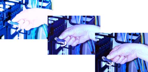
based upon their condition at the cross-connect. 1) Acceptable Patch-Cord
Slack - The inspectors applied the "three-finger" guideline to determine
acceptable slack in the patch cord. That is, the inspector placed
three fingers at the point where the patch cord entered the horizontal
manager and was routed to the data-equipment port. Acceptable slack
of 5 inches or less resulted when the cord could be looped around
three fingers at that point patch-cords surveyed, 6% were found to
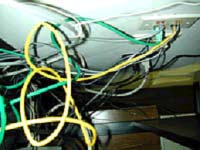
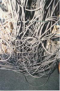
have acceptable slack (see figure 3). 2) Unacceptable Slack- Any length
of patch cord over the "three-finger limit" was deemed unacceptable.
The research found that 93% of all patch cords examined were too long.
The average overage per patch cord was 20 inches. Although this may
not seem like much, consider that, multiplied by 187, the average
number of patch cords per cross-connect, a total of 312 feet of patch
cord, longer than a football field, sits unused at each cross-connect.
This accumulated slack, hangs in disarray, affecting manageability,
aesthetics, bend radius, and bend-radius stability (see figure 3).
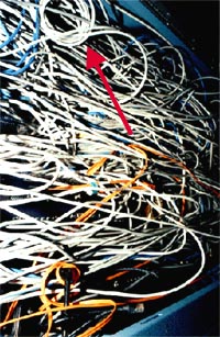
3) Kinked - This condition occurred when a patch cord was collapsed
on itself, bent 180 degrees, virtually without bend radius. In every
case, kinked patch cords, accounting for 2% of the total examined,
also had excessive slack (see figure 3). 4) Banjo - This condition
is found between the equipment port and the horizontal patch-panel
port when a patch cord that is too short is installed without benefit
of a vertical management system. One percent of the patch cords examined
had this problem (see figure 3). |
|
 |
| Figure 3 - Conditions of a Patch-cord |
|
| Inspectors found three types of horizontal patch-cord
managers in use, each of which affected bend radius differently. Distribution
rings were the most common way of directing the patch cords from the
patch panel to the vertical management system. Routing clips were
used at some sites. Smaller than distribution rings, they could be
more densely populated on the horizontal manager, allowing a straighter
patch. The third type of horizontal manager was the channel or duct
(see figure 4). |
|
 |
| Figure 4 - Typical Horizontal Managers |
|
|
|
| Figure 5 - Distribution Ring and Routing Clip
Distances Impact Patch-cord Bend Radius |
|
| If a strain relief or boot was present, the bend
might be sharpened even more when directing the patch cord into, say,
a 1-inch routing clip. Patch panels from some manufacturers also extended
0.5-inch out from their horizontal plane, further reducing the distance
between the distribution ring and patch panel. A vertical patch-cord
management system usually consisted of either brackets or channels
(see figure 6). The brackets came in many size and shapes, but often
comparable in size to their horizontal counterparts, even though required
to handle many more cables. Patch-cord bend radii was typically affected
by the "entangling effect" in the vertical managers. This phenomenon
occurs when someone relocates a patch cord and, instead of pulling
it out completely and starting over, he or she simply unplugs the
patch cord and sticks it into the new port atop the other cables (see
figure 6a). |
|
 |
Figure 6 - Typical Vertical Managers |
|
 |
 |
 |
Figure 6a - Entangling Effect |
|
|
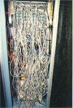
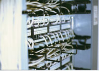
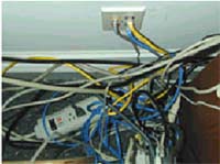
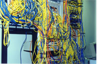
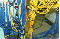
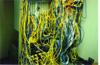
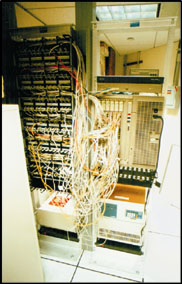
| In typical patch-cord management systems excessive
slack and lack of horizontal management at the concentrator (due to
height of concentrator) results in patch cords being compressed upon
another causing tight bend radius at the connector interface (see
figure 7) |
|
| Figure 7 - Compressed Patch-cord Radius |
 |
|
|
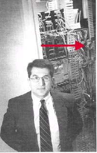
| Field Bend-Radius Analysis of Patch Cords |
| Inspectors evaluated the bend radius of each patch
cord by inserting a radius gauge at the points of the tightest bends.
Seventy-one percent of the 1624 patch cords evaluated had bend radius
at ¼" or less (see figure 8). |
|
 |
| Figure 8 - Patch-cord Bend Radius |
|
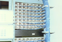
| Another issue in this area is bend-radius stability.
Unlike the situation in horizontal cable runs, where the cable is
stable once installed, patch cords may be moved constantly. A patch
occur measured on one day may have a different bend radius, or even
be kinked, the next day. This situation obviously does not apply to
the back of the patch panel, where horizontal cabling can be secured
from movement (see figure 9). |
|
|
Termination Spaces
- Cable Secured
- Special Tools Required
- Trained Personal
|
|
Patch-cords
- Movement Must Occur
- No Tools
- Plug/Play
|
 |
|
BACK
|
|
|
 |
|
|
|
FRONT
|
|
| Figure 9 - Bend-radius Stability |
|
| |
 |
 |
Uncontrolled
Bend Radius
(No bend radius stability)
Larger
Managers
|
|
|
| Figure 10 - How a Patch-cord is routed |
|
|
|
Insertion
and Removal
Insertion and removal
practices of patch-cords will result in repetitive bending (small
bend radius) at the patch-cord's plug as indicated in figure
11. |
|
| Figure 11 - Standard Patch-cord Practice |
|
 |
Previous TIA Contributions in the UTP systems working
group TR 42.7
- #414 - Patch-cord return loss by AMP
- #460 - Effects of service loops on CAT 6 link performance
by Microtest
Coiling of Patch-cord slack can have a negative effect
on return loss.
|
 |
|
| Figure 12 - Slack Contributes to Performance
Degradation |
|
| This research did not include the tight bending
that occurs in work area cords. This area is typically confined
and supports the use of tight bend radius (see figure 13). |
|
|
|
| Figure 13 - Work area cords |
|
|
| |
 |
|
|
Conclusion
|
|
The 87 cross-connect fields examined had adequate
vertical and horizontal wire managers, but did not eliminate or
minimize patch cord slack which contributed to poor management and
un-controlled bend radius.
A one-inch bend radius (2-inch diameter) of patch
cords was achieved only 7% of the time in a management field, as
where ¼ inch or less was measured 71% of the time. The standard
installation practice dictates that one-inch is an unachievable
and unrealistic requirement that cannot be met by patch cords in
the field.
Field
Recommendations for Patch Cords
Eliminate slack in each patch cord after routed
in a management system. This will provide the following benefits
to patch cord bend radius:
- Control bend radius (bend-radius stability)
- Reduce compressed patch cords at the connector
interface
- Provides better functional performance.
TR42.1 Committee Reaction
The committee was posed with an open floor to any
questions of the field analysis provided on bend radius. No committee
members responded.
|
|
|
Authored by: Dennis W. Mazaris, RCDD
Submitted: TIA/EIA TR-42.7 contribution #448, March 2000
Submitted: BICSI Standard Committee, August 1999 |
| |
| White paper -
TIA/EIA TR-42.7 contribution - Testing |
PerfectPatch Copyright
 2009 by PerfectPatch, Inc. All rights reserved.
 |
|
| |