
|
 |
|
|
This white paper contribution is part of a two part contribution on bend- radius analysis for patch cords that was submitted and presented at the March 2nd 2000, EIA/TIA, TR 42.1 committee meeting in Orlando, Florida. The contributions for testing and field analysis of bend radius provided the support for the TR 42.1 committee to provide a two-third vote to adopt a one times (1x) the cable diameter for UTP patch cords, bend radius in the future 568-B.1 standard. This new standard is to be ratified by the end of this year. |
| Patch-cord Testing |
 |
|
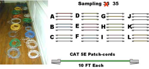
Patch-Cord Testing Series Patch-Cord Sampling |
| Two Bend Patch-cord Testing Series |
 |
|
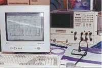
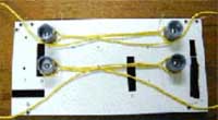
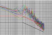
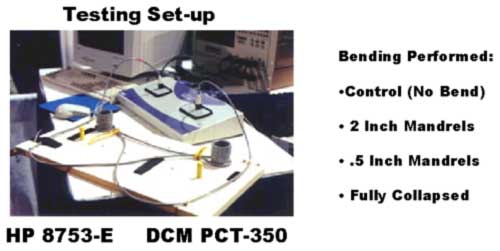
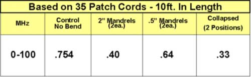
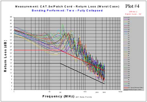
Patch Cord Testing Procedure Using the DCM PCT-350 System, which includes an automatic balanced switching device with a high-frequency interface combined with a HP 8753-E network analyzer and computer, Return Loss was measured to the Category 5e (568-A-5 standard) for patch cords. A jig was used with two, 2-inch mandrels (1-inch radius - 4 times the cable diameter) based on 0.25-inch maximum size diameter for UTP-four pair patch cables. 0.5-inch mandrels (.25 inch radius) were used to measure one times the cable diameter. All the bending was performed in a set of two (180-degree bends) on each patch cord under test. The following measurements were taken and recorded
in plots 1 through 4 after the cords were secured in place. All
35 patch cords were tested individually in each of the four measurement
states (below) for a total of 140 tests. After all cords were tested under the four different measurement states, they were combined into comparison analysis -- plot #5. |
| Lowest Margin from CAT5E Patch-cord Limit Line (MHz) |
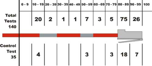 |
| Average Worst Case Margin.from CAT5e Patch Cord Limit Line |
|
Patch-Cord Testing Series Conclusion As indicated in the summary analysis (plot #5) the fully collapsed cords measured a 1.14 dB loss (average) when compared against the control cords (average). This indicates that this measurement state (fully collapsed) must be taken into consideration during patch- cord testing procedures. Supporting Contribution TIA TR-42.7.2 - Patch Cord Minimum Bend Radius, #028 by CommScope Recommendations for Patch Cords Testing To protect the consumers from field installations practices provide that fully collapsed cord test be inserted into the Mechanical Handling Stress Test as defined in the 568-A-5 standard (printed below). G.8 Mechanical handling stress test Modular patch cords shall comply with the return loss requirements of 6.3.1 after each step listed below. For all test conditions, a maximum 150 mm (6.0 in) of undisturbed cable shall be allowed to enter the test fixture at both ends. 1. Test the patch cord uncoiled. |
|
|
|
 |
|
|
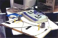
Channel Testing Series Utilizing the same testing equipment as used in the previous Patch Cord Testing Series and selecting previously profiled cords, two cords (10 ft.) were inserted into a 90-meter basic link to establish a channel. Although the patch cords were inserted into a channel, we also provided basic link measurement limits when testing for comparison. The basic link limits are more stringent (after 20 MHz) for RL than channel. A total of five different channels were constructed from the same 90-meter link utilizing ten different cords that were pre-qualified (profiled). A jig was used to provide controlled bending (180-degrees) two cords installed in the constructed channel. A total of four bends was applied (two on each cord) and measurements taken to Category 5e channel and basic link requirements. The following measurements were taken and recorded in plots 1A through 4A after the cords were secured in place for each of the five channels. - Control measurement - no bends (measurement #1A,
plot 1A) After all five channels were tested under the four different measurement states they were combined into comparison analysis -- plot 5A. |
| Lowest Margin From CAT5E Channel Limit Line (MHz) |
|
|
|
Channel Testing Series Conclusions The channel limit is the most important factor when testing components of a system. Due to the fact that the sum of all individual components in a channel do not add up to the performance of that channel, it is imperative that the channel be tested with the cords used for that channel. This will reflex the interaction and provide the true performance of that channel. The effects of return loss on the degree of bending patch cords in a channel has no direct correlation to performance. As indicated in the testing of four, one-inch radii (2-inch mandrels) inserted in a channel was the worst in performance of the different degrees of bends applied and still had a 1.18 dB margin over the more stringent Category 5e basic link limits when tested in a channel. |
|
|
|
 |
|
|
|
|
Patch Cord Channel Recommendation Provide a minimum bend radius, under no load conditions of one times (1x) the cable diameter for 4-pair UTP patch cords. TR 42.1 Committee Response The committee ratified the above recommendation by two third votes in the favor of a one-time the cable bend radius (1x) for UTP patch cords. |
| Home | Design & Installation | Programs | Instructions | Distributors | The Developers | Gallery | Questions | Email Us |
| PerfectPatch |